Voith Schneider Propeller Types and Dimensions - Voith Turbo
Voith Schneider Propeller Types and Dimensions - Voith Turbo
Voith Schneider Propeller Types and Dimensions - Voith Turbo

Create successful ePaper yourself
Turn your PDF publications into a flip-book with our unique Google optimized e-Paper software.
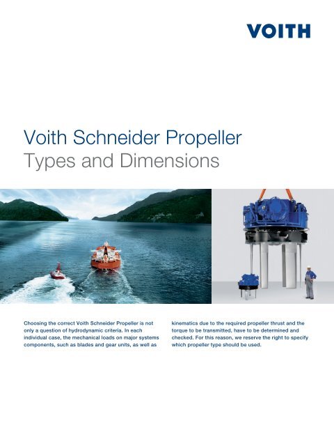
<strong>Voith</strong> <strong>Schneider</strong> <strong>Propeller</strong><br />
<strong>Types</strong> <strong>and</strong> <strong>Dimensions</strong><br />
Choosing the correct <strong>Voith</strong> <strong>Schneider</strong> <strong>Propeller</strong> is not<br />
only a question of hydrodynamic criteria. In each<br />
individual case, the mechanical loads on major systems<br />
components, such as blades <strong>and</strong> gear units, as well as<br />
kinematics due to the re quired propeller thrust <strong>and</strong> the<br />
torque to be transmitted, have to be determined <strong>and</strong><br />
checked. For this reason, we reserve the right to specify<br />
which propeller type should be used.
<strong>Propeller</strong> <strong>Types</strong> <strong>and</strong><br />
Main <strong>Dimensions</strong><br />
18 R 5 EC /150 -<br />
1<br />
propeller type<br />
blade orbit diameter in dm<br />
32 R 5 / 265 - 2<br />
propeller type<br />
blade orbit diameter in dm<br />
electronic control<br />
number of blades<br />
number of blades<br />
gear steps<br />
blade length in cm<br />
Our current production program contains<br />
different types:<br />
Type R4 EC, R5, R5 EC(R+S), R6 EC(R)<br />
gear steps<br />
blade length in cm<br />
Type R5 EC / … -1<br />
D<br />
Type R5 / …-2<br />
D<br />
E<br />
F<br />
F<br />
C<br />
C<br />
H<br />
H<br />
VSP<br />
32R5 / 265-2<br />
Prop.no.<br />
Year built<br />
G<br />
B<br />
ø A J<br />
I<br />
G<br />
B<br />
ø A J<br />
I<br />
4068<br />
2011
The table features the most important dimensions, weights<br />
<strong>and</strong> mo ments of inertia referring to the vertical axis of rotation<br />
<strong>and</strong> the oil filling of the propellers in our current production<br />
program.<br />
<strong>Propeller</strong><br />
type/size<br />
A = blade orbit diameter<br />
B = blade length (st<strong>and</strong>ard)<br />
C = number of blades<br />
D = height (input shaft)<br />
E = pinion offset<br />
F = length (input shaft)<br />
G = total height (propeller)<br />
H = well height<br />
I = casing outside diameter<br />
J = rotor casing outside diameter<br />
A<br />
mm<br />
B<br />
mm<br />
C<br />
no.<br />
D<br />
mm<br />
E<br />
mm<br />
F<br />
mm<br />
G<br />
mm<br />
H<br />
mm<br />
For a preliminary size determination in the initial project stage,<br />
a propeller se lection according to the max. pro peller input<br />
power as per the table above is possible. This table also states<br />
the permissible input speed ranges.<br />
I<br />
mm<br />
J<br />
mm<br />
Weight<br />
without<br />
oil<br />
abt. kg<br />
Oil<br />
filling<br />
abt. l<br />
Moment of<br />
inertia of rotor<br />
including<br />
additional<br />
water*<br />
kgm 2<br />
Max.<br />
propeller<br />
input<br />
power*<br />
kW**<br />
* The exact limit values must be established in consultation with<br />
us for the individual case of application.<br />
** 1st value full continuous load rating 2 nd value intermittent<br />
load rating (e.g. VWT)<br />
<strong>Propeller</strong><br />
input<br />
speed*<br />
abt. rpm<br />
10EG/65 1000 650 4 395 0 668 969 242 1390 1274 1960 140 160 180 900<br />
12R4 EC/90-1 1200 912 4 550 0 1020 1185 310 1660 1532 3800 380 460 260 1000<br />
16R5 EC/120-1 1600 1213 5 815 0 1100 1372 410 2145 2021 6700 680 2000 540 670<br />
18R5 EC/150-1 1800 1512 5 950 0 1280 1480 450 2405 2264 9500 1000 3080 780 570<br />
21R5/150-2 2100 1516 5 1100 360 1667 1755 500 2815 2640 16000 1600 6600 950/1000 700-1700<br />
26R5/195-2<br />
26R5/195-2 AE45<br />
28R5/210-2<br />
28R5/210-2 AE50<br />
2600 1965 5 1340<br />
2800 2115 5 1370<br />
400<br />
450<br />
450<br />
500<br />
1970<br />
2045<br />
2135<br />
2252<br />
1980 660 3435 3240<br />
2075 670 3710 3480<br />
27500<br />
28500<br />
33000<br />
34500<br />
2700 20800 1350/1500<br />
720-1200<br />
1200-1800<br />
3200 29500 1700/1900 720-1200<br />
1200-1600<br />
28R5/234-2 2800 2355 5 1455 450 2215 2168 730 3790 3560 36000 3700 29800 1850/2000 720-1200<br />
28R5 ECS/234-2 2800 2355 5 1455 500 2332 2400 730 3790 3560 38500 3700 29800 1850/2000 720-1600<br />
30R5/265-2 3000 2666 5 1580 500 2330 2380 750 4000 3780 47000 4000 44000 2250/2450 720-1200<br />
32R5/265-2 3200 2666 5 1580 560 2475 2373 750 4250 4000 54000 4600 55000 2500/2600 720-1200<br />
32R5 ECS/265-2 3200 2666 5 1580 560 2475 2373 750 4250 4000 54000 4600 55000 2500/2600 720-1200<br />
32R5 ECS/300-2 3200 3016 5 1580 560 2475 2563 750 4250 4000 54000 4600 55000 2500/2600 720-1200<br />
36R6/265-2 3600 2672 6 1900 630 2730 2820 900 4770 4490 76000 7500 104000 3050/3400 720-1050<br />
36R6 ECR/285-2 3600 2872 6 1990 710 2840 2965 950 4765 4490 88000 7500 114000 3800/3900 700-1200<br />
36R6 ECR/300-2 3600 3022 6 1990 710 2840 2965 950 4765 4490 86000 7500 114000 3800/3900 700-1200
<strong>Propeller</strong> Well<br />
The foundation for the <strong>Voith</strong> Schnei der <strong>Propeller</strong>, the so-called<br />
propeller well, consists of a cylindrical shell with a flange. The<br />
propeller well must form an integral part of the bottom structure<br />
of the vessel so that, in addition to the propeller weight,<br />
the forces <strong>and</strong> moments resulting from the propeller thrust<br />
can also be transmitted without stress concentrations in the<br />
<strong>Propeller</strong><br />
type/size<br />
<strong>Voith</strong> <strong>Turbo</strong> <strong>Schneider</strong> Propulsion<br />
GmbH & Co. KG<br />
P.O. Box 2011<br />
89510 Heidenheim, Germany<br />
Tel. +49 7321 37-4099<br />
Fax +49 7321 37-7580<br />
vspmarine@voith.com<br />
www.voithturbo.com/marine<br />
K<br />
mm<br />
O<br />
N<br />
L<br />
number<br />
P<br />
R<br />
25<br />
I<br />
K<br />
25<br />
N M L<br />
10EG/65 1350 27 16 1282+3 1296 8 18<br />
12R4 EC/90-1 1620 30 18 1540+4 1555 10 12<br />
16R5 EC/120-1 2110 36+9 18 2032+5 2048 10 21<br />
18R5 EC/150-1 2360 42+15 22 2275+5 2291 12 24<br />
21R5/150-2 2760 48 26 2655+5 2675 12 28<br />
26R5/195-2<br />
26R5/195-2 AE45<br />
28R5/210-2<br />
28R5/210-2 AE50<br />
28R5/234-2<br />
28R5 ECS/234-2<br />
M<br />
mm<br />
N<br />
mm<br />
3380 54+15 27 3260+5 3280 14 30<br />
3640 60 27 3500+5 3530 14 35<br />
3720 60+15 27 3580+5 3610 14 35<br />
30R5/265-2 3930 60+21 27 3800+5 3828 16 40<br />
32R5/265-2<br />
32R5 ECS/265-2<br />
32R5 ECS/300-2<br />
36R6/265-2<br />
36R6 ECR/285-2<br />
32R6 ECR/300-2<br />
2 mm<br />
flat seal<br />
H<br />
O<br />
mm<br />
K = bolthole circle diameter<br />
L = number of bolts<br />
M = bolthole diameter<br />
N = well diameter<br />
O = well shell diameter<br />
P = well shell thickness<br />
R = casing flange thickness<br />
ship’s hull. It has to be taken into account that the propeller<br />
thrust can vary by a full 360°, i.e. over the entire horizontal<br />
plane.<br />
The structural design of the well is shown in the figures above.<br />
The dimensions, as well as the permissible tolerances for the<br />
individual propeller sizes, are included in the table on the right.<br />
4150 66+21 33 4020+5 4050 16 40<br />
4680 72+21 39 4515+5 4550 18 50<br />
P<br />
mm<br />
R<br />
mm<br />
G 1997 e 10/2011 KO/WA 3 000 Printed in Germany. Subject to modifications.