- The following step-by-step instructions are part of the whole procedure of how to include GCPs in the project. For more information about how to include GCPs in the project: How to include GCPs in the project.
- All GCPs must be in the same coordinate system.
A ground control point (GCP) is a point of known coordinates in the area of interest. Its coordinates have been measured with traditional surveying methods or have been obtained by other sources (LiDAR, older maps of the area, web map service).
Ground control points can be used in Pix4Dmapper to increase the absolute accuracy of the project.
Add / import coordinates of the GCPs
Important:
The GCPs can be imported into the software using one of the following methods:
1. Using the GCP/MTP Manager: before running step 1. Initial Processing.
1. On the Menu bar, click Project > GCP/MTP Manager...
2. Select the GCP coordinate system: By default, the GCP coordinate system will be the same as the Output/GCP Coordinate System selected when creating the project: Step 2. Creating a Project. If the GCPs have a different coordinate system, select the correct coordinate system: How to select / change the Image / GCP / Output Coordinate System.
3. Import the GCPs coordinates. The GCP coordinates can be imported:
In order to import the GCPs one by one:
1. On the GCP/MTP Manager, click Add Point.
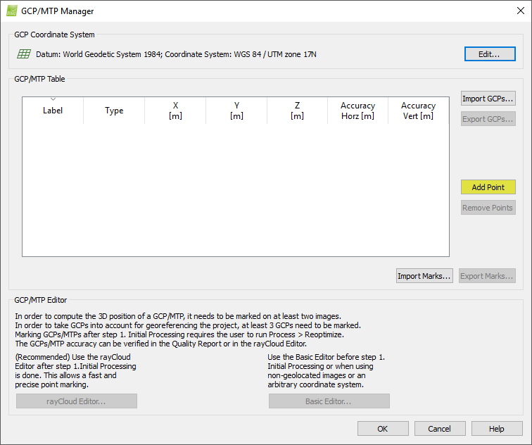
A new point is added on the GCP/MTP Table. This point is defined by default as Manual Tie Point (Type column) and is named by default mtp1 (Label column). When adding more Manual Tie Points, they will be named mtp2, mtp3, etc.
2. Edit the GCP properties:
- (Optional) Change the Label of the GCP:
1. Double click the Label cell of the point.
2. Type the desired name.
- Change the Type of the GCP:
1. Double click the Type cell of the point.
2. From the drop down list select:
- 2D GCP: if only the X,Y or Latitude,Longitude coordinates of the GCP are known.
- 3D GCP: if the X,Y,Z or Latitude, Longitude, Altitude coordinates of the GCP are known.
- Check Point: if the X,Y,Z or Latitude, Longitude, Altitude coordinates of the GCP are known. A Check Point is not used in the reconstruction and indicates the accuracy around the areas where it is defined.
- Insert the GCP coordinates:
1. Double click the coordinates cells of the point (X,Y,Z or Latitude, Longitude, Altitude).
2. Type the corresponding coordinates.
- (optional) Insert the Accuracy (for 2D GCP Accuracy Horz, and for 3D GCP Accuracy Horz and/or Accuracy Vert):
Warning: The default value is 0.020 m, DO NOT modify the accuracy, unless the following article is read: GCP / Manual Tie Point Table.
1. Double click the Accuracy Horz/Vert cell of the point.
2. Type the Accuracy of the point:
- For very accurate GCP, insert a low Accuracy value.
- For non accurate GCP, insert a high Accuracy value.
For more information about the GCP table properties: GCP / Manual Tie Point Table.
3. Repeat steps 1 and 2 for the rest of the GCPs.
4. On the GCP/MTP Manager window, click OK.
In order to import the coordinates from the GCP file:
1. Make sure that the GCP file has the correct input file format. For more information about the file format: Input files.
2. On the GCP/MTP Manager window, on the GCP/MTP Table, click Import GCPs...
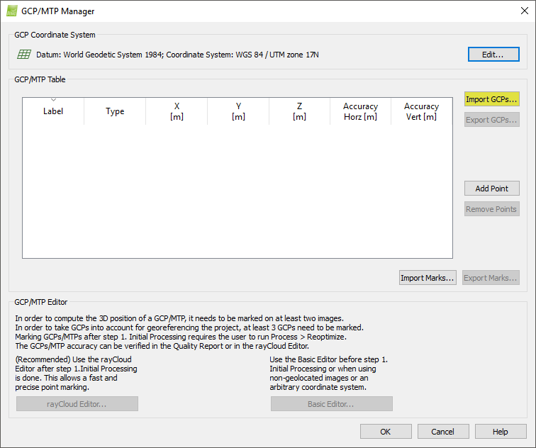
The Import Ground Control Points pop-up appears.

3. (optional) Select the Coordinates Order: By default, X, Y, Z (Latitude, Longitude, Altitude) is selected. It is possible to change to Y ,X, Z (Longitude, Latitude, Altitude). For more information: Input files.
4. Click Browse... to navigate to the GCP file.
5. Select the GCP file.
6. Click Open.
7. (optional) Insert the Accuracy (for 2D GCP Accuracy Horz, and for 3D GCP Accuracy Horz and/or Accuracy Vert):
Warning: The default value is 0.020 m, DO NOT modify the accuracy, unless the following article is read: GCP / Manual Tie Point Table.
1. Double click on the Accuracy Horz/Vert cell of the point.
2. Type the Accuracy of the point:
- For very accurate GCP, insert a low Accuracy value.
- For non accurate GCP, insert a high Accuracy value.
For more information about the GCP table properties: GCP / Manual Tie Point Table.
9. On the GCP/MTP Manager window, click OK.
2. Using the rayCloud: after step 1. Initial Processing has been completed.
1. On the Menu bar, click Project > GCP/MTP Manager...
2. Select the GCP Coordinate System: How to select / change the Image / GCP / Output Coordinate System.
3. Open the rayCloud: From the Menu bar, click View > rayCloud. The rayCloud opens and the Automatic Tie Points appear.
4. On the 3D View, click on one point that approaches the GCP position.
Note:
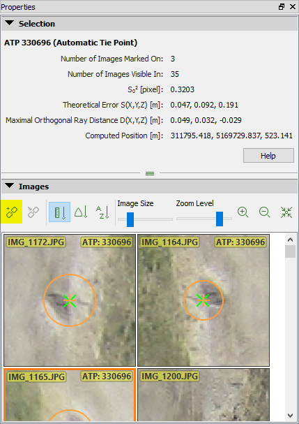
- On the right sidebar, the Images section displays all the images on which the clicked (selected) point is visible.
- On all the images the following appear:
- Green cross: Reprojection of the 3D point on the images.
- Orange cross: Position where the associated 2D keypoints have been automatically detected.
- Orange circle: The radius of the orange circle indicates the size of the area that has been taken into account to detect the keypoint.

5. On the right sidebar, in the Images section, the GCP area should appear in the displayed images. If not, click another point on the 3D View that approaches better the GCP area.
6. Click  New Tie Point.
The Selection section in the right sidebar displays information about the New Tie Point:
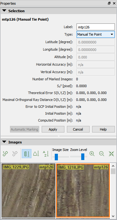
7. Edit the point's properties:
- (optional) Change the Label of the GCP:
1. Click the Label cell of the point.
2. Type the desired name.
- Change the Type of the point:
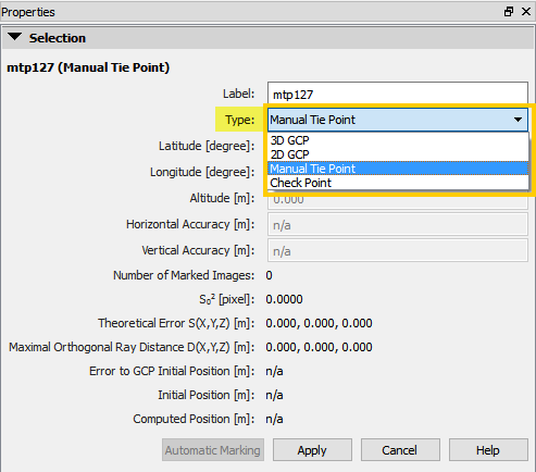
1. From the drop down list select:
- 2D GCP: If only the X,Y or Latitude,Longitude coordinates of the GCP are known.
- 3D GCP: If the X,Y,Z or Latitude, Longitude, Altitude coordinates of the GCP are known.
- Check Point: If the X,Y,Z or Latitude, Longitude, Altitude coordinates of the GCP are known. A Check point is not taken into account during processing and indicates the accuracy around the areas where it is defined.
- Insert the coordinates of the GCP (for 2D GCPs and 3D GCPs):
1. Click the coordinates cells of the point (Latitude, Longitude, Altitude or X,Y,Z).
2. Type the corresponding coordinates.
- (optional) Insert the Accuracy (for 2D GCP Horizontal Accuracy, and for 3D GCP Horizontal Accuracy and/or Vertical Accuracy):
Warning: The default value is 0.020 m, DO NOT modify the accuracy unless you have read: GCP / Manual Tie Point Table.
1. Click the Horizontal Accuracy / Vertical Accuracy cell of the point.
2. Type the Accuracy of the point:
- For very accurate GCP, insert a low accuracy value.
- For non accurate GCP, insert a high accuracy value.
For more information about the GCP table properties: GCP / Manual Tie Point Table.
8. Click Apply.
9. Repeat steps 4 to 8 for other GCPs.
Mark / click GCPs on the images
The GCPs can be marked in the software using one of the following methods:
1. Using the rayCloud: when GCPs refer to a known coordinate system and after step 1. Initial Processing has been completed.
1. Open the rayCloud: On the Menu bar, click View > rayCloud.
2. On the left sidebar, in the section Layers, click Tie Points, then click GCPs / MTPs. The list of GCPs is displayed:
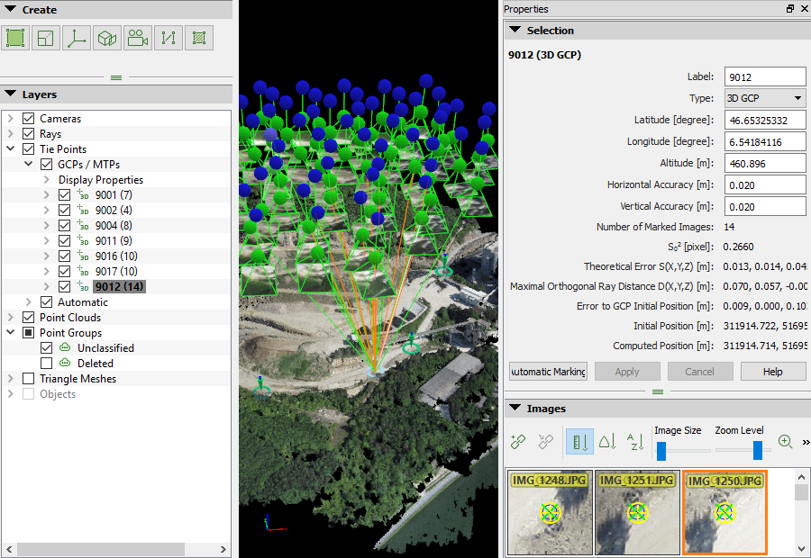
3. Select a GCP in the layer GCPs / MTPs: the right sidebar displays its properties and the list of images in which it is visible.
Note: On the right sidebar, in the section
Images, all images in which a selected GCP is visible are displayed.
The estimated GCP position appears on the images with a blue circle with a dot in the middle. This position corresponds to the projection of the input 3D coordinates of that GCP in one particular image.
The estimated GCP position appears on the images with a blue circle with a dot in the middle. This position corresponds to the projection of the input 3D coordinates of that GCP in one particular image.
4. Navigate on the images to find the exact location of the GCP:
- Zoom in: Moving the mouse scroll wheel forwards.
- Zoom out: Moving the mouse scroll wheel backwards.
- Pan: Using the mouse left clicking.
- To change the size of the images: Move the thumb of Image Size bar.
5. Mark the exact position of the GCP on at least 2 images using the left mouse click.
Note:
- When marking a GCP on the images, all marks of this GCP are used to compute a new 3D point. At least 2 images need to be marked in order to compute the estimated 3D position of the GCP. This estimated 3D point is then reprojected in all the images where it might be visible in.
- The clicked position appears with a yellow cross and circle. The size of the yellow circle indicates the zoom level at which the marking has been done. Points that have been marked on a high zoom level are taken more into account than points that have been marked on a low zoom level.
- After marking a GCP on 2 images, a green cross appears on all images. The green cross represents the reprojection of the estimated 3D point and its location depends on the marks already made for the GCP.
- After marking a GCP on 2 images, a pink circle appears when the point is wrongly marked on other images. Outliers are indicated with pink circle and they do not influence the calibration results.
6. (Optional) Click Automatic Marking to automatically detect the position of the GCPs on the rest of the images.
Note: After running the Automatic Marking algorithm, we recommend checking the position of the automatically detected marks in order to assure they are positioned correctly. Refine the position of automatically detected marks if needed.
7. When the green cross is at the correct position in most images, click Apply.
8. Repeat steps 3. to 7. for the rest of the GCPs.
9. When all GCPs are marked on the images, click Process >Reoptimize. This reoptimizes the reconstruction using the GCPs.
Note: For more information about the Reoptimize option:
Menu Process > Reoptimize.

10. (optional) To Generate a new Quality Report, click Process >Generate Quality Report.
2. Using the Basic GCP/MTP Editor: when the GCPs coordinate system is Arbitrary or before running step 1. Initial Processing.
1. On the Menu bar, click Project > GCP / MTP Manager...
2. On the GCP/MTP Manager, click Basic Editor..., the Basic GCP/MTP Point Editor window appears.
3. On the GCP/MTP Table, select the GCP to be marked.
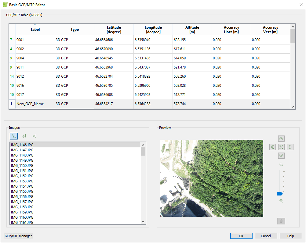
4. On the Images section, sort the image list:
 By name: The images are sorted alphabetically.
 By Distance to GCP: Images closer to the GCP are listed first. This sorting can be used only if the images and GCPs are geolocated using a known coordinate system. This is the default sorting mode.
 By Distance to the Marked Image: When an image is selected and a GCP is marked on it, this option lists the images that are closer to the currently selected image. This sorting can be used only if the images are geolocated.
5. On the Images section, select the image on which the GCP should be marked. After the selection, the image is displayed in the Preview section.
6. Navigate in the image by:
- Zoom in: Moving the mouse scroll wheel forwards.
- Zoom out: Moving the mouse scroll wheel backwards.
- Pan: Using the mouse left click.
- Zoom in quickly on a specific point in the image: point with the mouse the point and press the Alt key. When the key is released, the view returns to the last zoom level.
- Zoom out to preview the zero zoom level: Press the Shift key. When the key is released, the view returns to the last zoom level.
7. Left click on the image to mark the point.
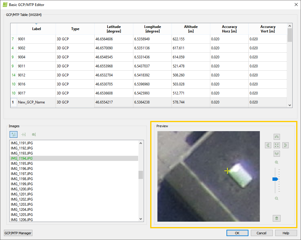
8. (optional) If it is needed to remove a mark, click  Remove.
9. On the Images section, select the next image on which the GCP should be marked.
Note: A GCP does not need to be identified / marked on all images in which it appears. Ideally, mark a GCP on 3 to 8 images (the minimum number of images is 2). The Q
uality Report after step
1.Initial Processing indicates if it is needed to mark the GCP on more images.
10. Repeat steps 5 to 9 for other GCPs.
11. Click OK.