im trying to connect it this way: (althoug the next image is a 5V relay im using the 12V one, it waas easy to find the image of the 5V but my relay is the 12V one)
If I connect the DC+ and DC- to the arduino directly, the green light of pwer from the relay turn on, and with the blink program the red light of the relay is turning off and on and the blink in the arduino is also working(i added the blink in both arduino and relay ti see what happens), so the signal from pin 8 attached to the In in the relay is working, but the click is not working, so I suppose that the arduino is 5V and the relay is 12V so i need a 12v power suply.
So I changed the DC+ and DC- to the 12V power suply and turn on the power suply and the arduino, both of them turn on, I have the green light of the relay ok, but now the blink program only does the blink on the arduino, the blink red light which was working on the DC+ and DC- with the arduino now is not working.
Im coonecting everything directly, since im using a 12V power supply and the relay has the optocoupler, i dont need anything else, but I want to hear the magic click
can any1 tell me what im doing wrong? (in newbie talk) thanks!
You have provided only half of the hook-up information. Your diagram does not show the connections to the arduino and the connections of power to the arduino and the arduino to the relay module. The complete picture is important to debug the complete system.
The conections are Direct as i described un muy post.
The vcc first i tried to arduino and ir works but the relay does not activate, the power turns on, and the blink program light the red light in the relay with pin8, but the relay does not click.
O changed the VCC yo a 12v power supply and the power in the relay turns on bit the blink doesnt
I haven't used this relay module and haven't been able to find a diagram for it, but let me offer a suggestion that might help (if you haven't already tried it!)
Disconnect your relay module from everything.
Move the "Level Trigger" jumper on the module to the "L" position.
Connect the relay module to your 12V power supply.
Take a short piece of wire and briefly connect the "IN" point on the module to "DC-."
Did the relay click? If so, you know your relay module is OK.
If that works, we can proceed to try and connect the module to your Arduino -- let us know!
oplaza:
The conections are Direct as i described un muy post.
The vcc first i tried to arduino and ir works but the relay does not activate, the power turns on, and the blink program light the red light in the relay with pin8, but the relay does not click.
O changed the VCC yo a 12v power supply and the power in the relay turns on bit the blink doesnt
I don't see any power supplies in the OP. the drawings do not show how the arduino is powered. It does not show how the grounds are connected. The drawings are not complete. As you see you have received half responses due to the half information provided. I can make suggestions on what to do, but if your setup is don't connected properly then things will be damaged.
The Arduino output is only 5v , so you need a transistor switch to operate this relay and give a 12v signal to its signal input . You would better off buying the 5v version
OK! And I assume that your Arduino is working fine too and your BLINK program is turning your Arduino LED on and off. Leave your working relay module disconnected for now.
Now: make sure that your program is binking the LED only about once per second -- slow! And verify that the Arduino pin you want to use to drive your relay module is in fact switching between a high voltage and a low voltage as your LED blinks. Do you have a way to do that?
hammy:
The Arduino output is only 5v , so you need a transistor switch to operate this relay and give a 12v signal to its signal input . You would better off buying the 5v version
CurtCarpenter:
OK! And I assume that your Arduino is working fine too and your BLINK program is turning your Arduino LED on and off. Leave your working relay module disconnected for now.
Now: make sure that your program is binking the LED only about once per second -- slow! And verify that the Arduino pin you want to use to drive your relay module is in fact switching between a high voltage and a low voltage as your LED blinks. Do you have a way to do that?
Let me try yo understand first, What u tring to say is that to activate the relay i have to transmit also 12v to that pin? Even though I have a external power supply?
If so i have one question i want to activate /deactivate a door eletronic device with 12v, if im able to transmit 12v to something director, what do i need the relay for?
No no -- you don't need to transmit 12V. You need to measure the voltage on the IN pin of your relay module so we can be sure you don't damage your Arduino when you connect to it.
You don't want to connect your relay module directly to your Arduino, as it will eventually damage it. Hammy is right: you either need to add some circuitry between your Arduino and your relay module, or you need to buy a 5 volt relay module.
I've attached a diagram of the circuit you need to add between your 12V relay module and your Ardquino.
(Note: the 12V + terminal of your power supply will also be connected to the COM pin on your relay module. Your load -- the thing you're trying to control -- will be connected between the "NO" point and the - terminal of your 12V power supply).
Hope that helps. I'd probably go with hammy's recommendation and buy a 5V version of your relay module, which will connect directly to your Arduino without that extra circuitry.
No, sadly the s8550 is a "PNP" transistor and you need an "NPN" type. Just about any small NPN type transistor will work. The resistor in the diagram can be anything from about 1K to 10K ohms -- it's not critical for you either.
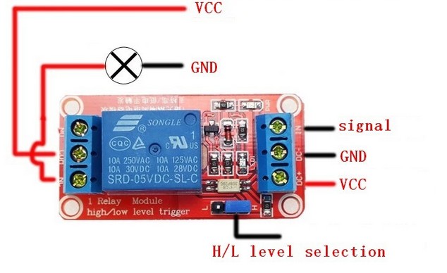
If you buy a 5V relay module, you can connect it directly to your Arduino via its IN terminal, and use its "N/O", "COM" and "NC" terminals to turn anything ON and OFF. Maybe this diagram will help you to understand what is going on:
This figure is not EXACTLY how your relay module is wired up, but it will give you the basic idea of how it works. Note that the NO/COM/NC contacts on the relay are entirely separated from the circuitry that controls them.