The labels of the input pins are hidden in the images they supply. The input pins are 'DC-', 'DC+', and 'IN'.
The only hookup that makes sense is to provide 12V to the DC+ and DC-. The module and Arduino must share a common ground. A pin from Arduino will drive the 'IN' input. But will it work? Or, do you suggest I set it aside and order a 5V relay module?
Post a cell phone photo of the side that has the jumper so we can see what it says. Typically there is a jumper that allows you to isolate the module with an opto coupler. Either way, we need to see the jumper
label.
Nevermind. I found it on Aliexpress. Apparently the jumper is the H/L level trigger select. I could be wrong
but I guessing that's the vendor's way of saying ACTIVE HIGH or ACTIVE LOW. (meaning you turn the relay on with HIGH (5V) or with a low (0V) from the arduino.
Yes, I'm quite sure you can use this with an Arduino.
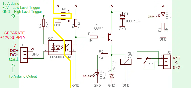
The module has a relay with 12V coil, so a separate 12V power supply is needed. It's a good thing to have a separate supply anyways, because if you're controlling a higher voltage AC load, the added opto isolation gives a much needed benefit.
I believe the circuit would be the same as below, but you would connect the 12V supply to DC+ and DC-.
The arduino connections would be the middle pin (jumper removed) for trigger. This would be connected to Arduino +5V (low level trigger) or GND (high level trigger). The IN1 or CH1 terminal connects to the Arduino output pin.
The module and Arduino must share a common ground.
No, because the Arduino is just powering an LED (IRLED).
If the GND of the 12V supply is connected to Arduino GND, it will still work, but opto-isolation will be lost.
Here are the notes I've made for future reference:
Two Relay Module designs exist.
Relay Module Design 1
Design 1 is distinguished by a jumper used on header-1 with three pins labeled "JD-Vcc", "Vcc", and "GND". A second header, header-2 has pins labeled "GND", "IN1", and "Vcc". An additional "INx" pin is provided for each relay on the module.
To hook up, first remove the jumper.
On header-1, attach a seperate voltage supply to "JD-Vcc" and "GND". For example, if using a 5V relay module, connect 5V to "JD-Vcc", and ground to "GND". (A 12V relay would use a 12V supply.)
On header-2, attach 'Arduino 5V' to "Vcc". Attach each GPIO pin from Arduino to each "INx" pin on the Relay Module. The relays will be activated by a "LOW" signal.
Each relay has outputs labeled "NO", "COM", and "NC". Attach these to the load as necessary. (For example, for a 12V Water Valve, use a 12V Supply with 12V power to "COM". "NO" attaches to the load's 12V input". The ground of the load is attached to the ground of the 12V supply.)
WARNING: Be sure to use a flyback diode across any loads with a coil, such as a water valve. Attach the cathode to the 12V input and the anode to the ground of the load device.
Relay Module Design 2
Design 2 is distinguished by a jumper used on header-1 with one pin labeled "H", the middle pin is unlabeled, while the third pin is labeled "L". A second header, header-2 has pins labeled "DC+", "DC-", and "CH1". An additional "CHx" pin is provided for each relay on the module.
To hook up, first remove the jumper.
On header-1, attach 'Arduino 5V' to the center, unlabeled pin.
On header-2, attach a seperate 5V supply with 5V to "DC+", and ground to "DC-". Attach Arduino GPIO pins to each "CHx" pin. The relays will be activated by a "LOW" signal.
Attach relay outputs as above.
There's at least one other, which is like your #2 (that is, no JD-Vcc) but with no jumper to select if it's active high or low. My one is active low, and I guess it's possible there's an active high one; so that's 3 or possibly 4 designs.